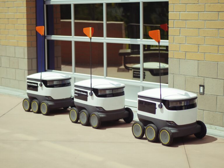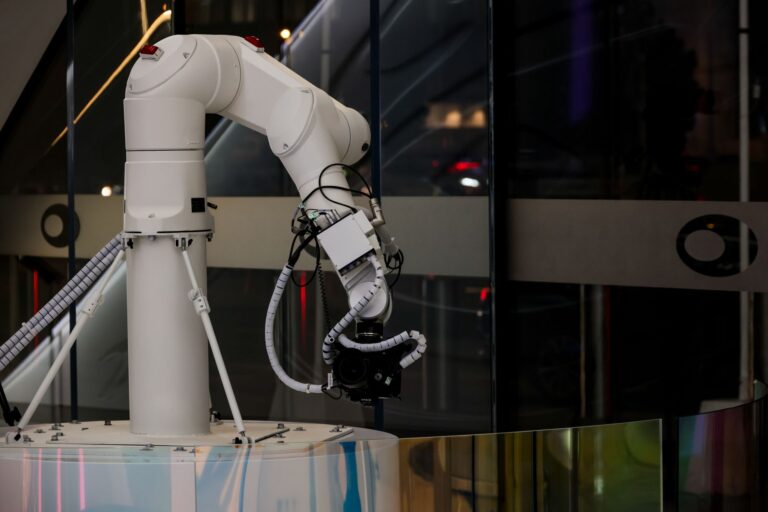

Construction layout robots are mobile machines that print building plans full-size directly on the floor slab. They translate digital layout files into ink marks for walls, doors, and service points exactly where crews will build them.
For site teams, the appeal is simpler layout with less tape and string work. The robot handles measuring and marking, while people still verify control, manage the model, and build the work. What follows explains the process, the practical effects, and the limits to weigh.
Table of Contents
- How does a floor-printing robot work?
- What does the crew still do by hand?
- Where do errors and site limits show up?
- How to judge fit for your project?
How does a floor-printing robot work?
The crew loads a layout file prepared from the project model. The file contains wall lines, openings, grid marks, and points for anchors, sleeves, or hangers. The robot then ties that file to fixed reference points in the building.
Once set, the machine moves across the slab and prints as it goes. It uses onboard sensors to track position and steer along the planned lines. Ink or removable markers show wall faces, centerlines, text labels, and symbols for different trades. A typical setup follows this order:.
- Clean the slab area and confirm control points are stable and visible
- Load the checked layout file and select the zone to print
- Let the robot localize, then watch the first marks for alignment
- Print the area in passes, keeping foot traffic and equipment clear
What does the crew still do by hand?
Robots reduce manual measuring, but they do not remove layout responsibility. Someone must prepare a clean model, remove clutter from the file, and confirm heights, offsets, and design changes. A wrong or outdated file will print wrong lines quickly. People also manage the floor itself.
Dust, water, curing compound, rough concrete, cords, and stored material can block travel or blur marks. A worker usually walks with the machine, moves small obstacles, protects fresh marks, and checks results against control. Verification stays human work. Crews spot-check printed lines with familiar tools before framing, drilling, or cutting. That check catches file errors, shifted control, and marks that are hard to read in site light.
Where do errors and site limits show up?
Most problems come from inputs, not the drive system. Control points can be bumped, floors can deflect or slope, and models can carry unresolved conflicts between structure, walls, and services. Each issue shows up as a clean-looking mark in the wrong place. Readability is another limit. Ink can fade under traffic, wash away with water, or blend into stains and patch marks.
Color coding helps, but only when every trade knows what each color and label means. A short legend at the site board prevents confusion. Access matters as well. Tight rooms, stairs, congested decks, and active work zones slow travel and force partial prints. Jobs with simple open floors gain more than jobs with many small changes, late revisions, or constant obstructions.
How to judge fit for your project?
Start with repetition and clarity of scope. Open offices, schools, hospitals, warehouses, and parking decks with repeated walls and many points often benefit most. One-off rooms with heavy field improvisation benefit less. Look at crew capacity and file quality next.
The best candidate has a reliable model, stable control, clean slabs, and someone able to own the layout file. Without those basics, the robot adds handling without removing rework. Run a small trial on one floor or wing before wider use. Compare setup time, print time, check time, and rework against hand layout. Keep the trial area protected and ask each trade whether marks were clear, complete, and easy to build from.