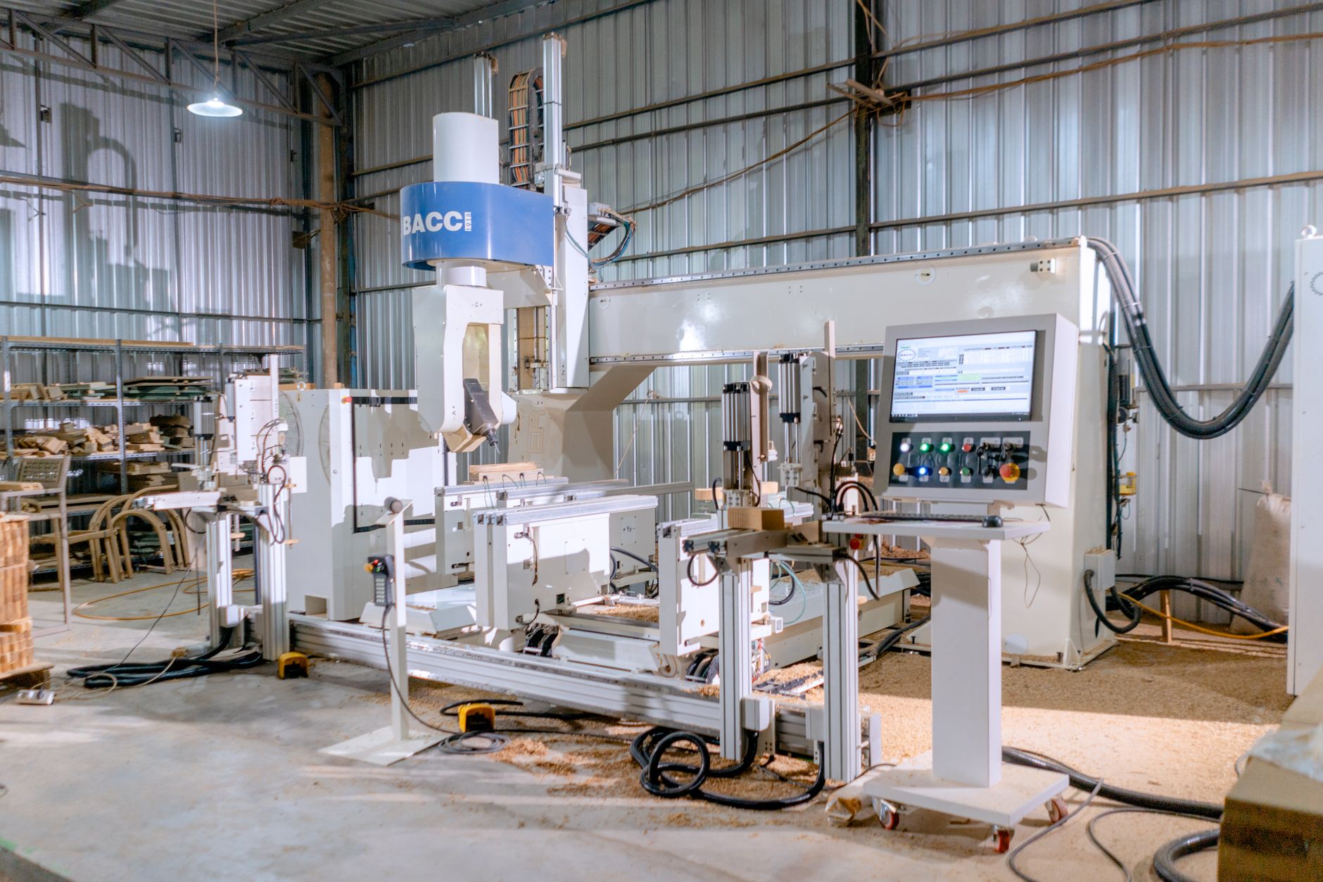

Upgrading CNC machinery through electrification means replacing legacy hydraulic, pneumatic, and mechanical systems with modern electric servo motors, drives, and controls that deliver greater precision, repeatability, and energy efficiency. This shift represents a fundamental change in how industrial automation systems operate at the machine level, moving from continuous-duty fluid power to discrete, electronically controlled motion. The upgrade isn’t merely swapping one motor for another—it requires rethinking the entire power transmission architecture, control logic, and integration strategy of equipment that may have operated reliably for decades.
Real-world electrification reshapes both capability and cost structure. A manufacturer that electrifies a legacy hydraulic press or multi-axis lathe typically gains sub-micron positioning accuracy, reduced energy consumption per cycle, lower maintenance frequency due to fewer leaking seals and fluid changes, and the ability to integrate real-time diagnostics and remote monitoring. The tradeoff is upfront capital investment, specialized technical expertise during transition, and the need to validate that mechanical components originally designed for hydraulic speeds and loads can handle electric servo dynamics.
Table of Contents
- Why Does CNC Machinery Require Electrification for Modern Automation?
- Core Electrification Techniques and Motor Selection
- Drive Systems and Control Integration
- Energy Efficiency and Thermal Management Trade-offs
- Mechanical Stress and Bearing Durability Issues
- Spindle Electrification for Precision and Speed
- Regenerative Braking and Power Management
Why Does CNC Machinery Require Electrification for Modern Automation?
Legacy CNC systems, particularly those built before the 2000s, often rely on hydraulic amplification to generate the force and speed needed for heavy cutting, pressing, or material handling. Hydraulic systems excel at delivering enormous force in compact spaces and inherently tolerate shock loads, but they leak oil, require routine fluid analysis, generate heat that demands cooling infrastructure, and introduce lag between electrical command and mechanical response. As manufacturing demand shifted toward faster cycle times, tighter tolerances, and lower downtime, the slowness and unpredictability of hydraulic response became a limiting factor.
Electrification addresses these constraints by placing electric servo motors and precision ball screws—or direct-drive linear motors—at the point of load. Each axis can now move independently, accelerate smoothly, and hold position without power consumption, unlike a hydraulic system that must maintain pump pressure constantly. A CNC vertical milling machine upgraded with electric servo spindle, ballscrew-driven axes, and regenerative braking on rapid traverses can cut cycle time by 20 to 40 percent while improving surface finish and tool life. The machine also becomes more compatible with Industry 4.0 frameworks: electric servo systems emit velocity and current feedback in real time, making it trivial to detect tool wear, spindle imbalance, or thermal drift before scrap parts pile up.
Core Electrification Techniques and Motor Selection
The choice of electric motor technology defines the entire upgrade strategy. Brushless AC servos deliver smooth, continuous torque across a wide speed range and pair naturally with industrial feedback devices like encoders or resolvers; they are the industry standard for precision positioning on CNC mills, lathes, and assembly gantries. Synchronous reluctance motors offer lower cost and simpler cooling but sacrifice some dynamic response.
Stepper motors work for lighter, slower applications like engraving or small-format routing but lack the torque density and speed range needed for production CNC work and are vulnerable to resonance issues at certain shaft speeds. The critical limitation of motor upgrade is the mechanical interface: existing ballscrews may have excessive backlash or runout, spindle bearings may be rated for lower speeds or accelerations than the new motor can deliver, and coupling resonance can amplify vibration if not carefully addressed. A manufacturer upgrading a 20-year-old turret lathe must often replace not just the spindle motor but also the spindle itself, the headstock bearings, and the control logic—a decision that blurs the line between “upgrade” and “rebuild.” Direct-drive rotary systems, where the motor shaft becomes the spindle shaft with no intermediate gearbox, eliminate backlash and resonance peaks but require careful thermal management because motor heat conducts directly into the cutting zone.
Drive Systems and Control Integration
Modern brushless servo drives convert DC bus voltage to three-phase AC current with switching frequencies typically between 10 and 20 kHz, creating a smooth torque profile and enabling precise speed regulation via feedback. The drive samples encoder position thousands of times per second, adjusts motor current in real time, and communicates back to the machine controller via Ethernet, CANopen, or PROFINET protocols. This tight loop between motion command and actual position makes CNC errors detectable within milliseconds, allowing the controller to halt or reverse motion if an obstacle is detected or if the load exceeds a preset limit.
Integration complexity arises when the legacy machine control (often ladder logic or proprietary firmware) must be replaced with modern software-based CNC kernels like Linuxcnc, Mach3, or industrial controllers from Siemens, Fanuc, or Haas. Some upgrades preserve the original control cabinet and wire a new servo drive stack in parallel, allowing phased transition; others require a full controller swap, which introduces risk if the machine’s geometry, tool library, or collision avoidance logic must be relearned. A common pitfall is underestimating the engineering effort to migrate part programs and calibration data—a machine that ran for years under the old control system may exhibit slight axis mapping differences or thermal compensations under the new one.
Energy Efficiency and Thermal Management Trade-offs
Hydraulic systems waste energy as heat in proportional control valves, line friction, and pump standby losses; typical hydraulic conversion efficiency is 60 to 70 percent. Electric servos reach 85 to 95 percent efficiency at rated load because the motor only draws current when accelerating or cutting, and energy braking resistors can recover some power during rapid deceleration. Over thousands of cycles per day, this efficiency gain compounds: a machine tool upgrade can reduce electrical consumption by 40 to 50 percent and eliminate the cost of hydraulic fluid top-ups, filter changes, and disposal.
The tradeoff is thermal concentration: while a hydraulic system spreads heat through its reservoir and cooling loop, a servo motor concentrates heat in the stator windings and rotor. If the machine operates in a warm ambient (above 35°C) or runs extended cycles without break, the motor will saturate thermally and derate, reducing available torque. Many electrified machines require forced-air cooling or even liquid cooling of the motor and drive enclosure. In tight shop floor spaces, adding a cooling duct or external chiller introduces maintenance burden and energy overhead that partially offsets the servo efficiency gain.
Mechanical Stress and Bearing Durability Issues
Electric servos deliver faster acceleration ramps than hydraulic systems—a servo can go from rest to full speed in 100 to 200 milliseconds, while a hydraulic system takes several seconds. This dynamic aggressiveness reveals hidden mechanical weakness: spindle bearings that tolerated years of smooth hydraulic ramp-up fail quickly under servo impulse loads, ballscrew preload nuts develop play, and belt drives chafe at harmonic frequencies that the old system never excited. A manufacturer that simply bolts a servo motor onto an ancient spindle coupling often faces catastrophic bearing failure within weeks of commissioning.
Proper electrification includes a mechanical audit and upgrade path. Spindle bearings rated for the servo acceleration profile, angular contact pairs preloaded to remove radial play, and ballscrew preload adjusted to eliminate backlash without excess friction are non-negotiable. Some shops upgrade to ceramic hybrid bearings, which tolerate higher speeds and thermal gradients, or switch to hydrostatic spindle bearings that float on an oil layer and eliminate rolling-element contact stress—but these options add cost and complexity. The lesson: do not assume mechanical geometry from the original machine will simply accept electric motion; budget time and money for thorough bearing and ballscrew replacement.
Spindle Electrification for Precision and Speed
The spindle—the rotating shaft that holds the cutting tool—is often the last component upgraded because it is the most critical and highest-consequence failure point. Direct-drive spindle motors, where the motor shaft rotates at cutting speed (typically 5,000 to 30,000 RPM for precision milling) without a gearbox, are increasingly common because they eliminate resonance peaks and backlash. However, they concentrate heat and vibration in a small package, requiring precision ceramic or hydrostatic bearings and tight thermal control.
Belt-drive spindles, using a servo motor connected via precision timing belt to the cutting spindle, are a simpler retrofit option for existing machines. They allow the motor to run at a less demanding speed (often 3,000 to 6,000 RPM) with lower thermal load, and belt slip absorbs some shock from tool engagement. The downside is belt wear, which introduces speed variation that degrades surface finish over time, and the need to periodically re-tension the belt. A CNC machine retrofitted with a servo-belt spindle system can achieve good results for general machining but will never match the stability and precision of a direct-drive electric spindle operating under closed-loop feedback.
Regenerative Braking and Power Management
When a servo axis decelerates from high speed—such as a rapidly moving gantry in a large horizontal boring machine or a spindle cycling down—the inertia of the load acts as a generator, pushing electrical energy back into the drive. Standard servo drives dissipate this energy in braking resistors, converting kinetic energy to heat in the cabinet. Regenerative systems instead route that energy back to the DC bus, reducing the total power drawn from the plant supply and lowering operating temperature inside the drive enclosure.
Regenerative capability depends on the drive architecture and the plant electrical service. Drives with active front ends and sine-wave output can feed power back into a three-phase supply; drives with simple rectifier input cannot. A machine tool that runs hundreds of rapid traverses per shift can justify the cost of regenerative hardware because the payoff compounds over years of operation. However, if the retrofit is on equipment that cycles slowly or spends most time cutting at steady state (as opposed to rapid acceleration-deceleration), the energy savings are marginal and regeneration hardware becomes an unnecessary expense.