
You build a DIY robot arm with Arduino by mounting three to six hobby servo motors on a rigid frame, wiring their signal lines to an Arduino board, powering the servos from a separate battery or adapter rather than the Arduino itself, and uploading a sketch that uses the Servo library to drive each joint to an angle. The build splits cleanly into four jobs — mechanical frame, servo selection, power and wiring, and control code — and the power stage is where most first attempts fail.
An Arduino is a small microcontroller board that runs one program at a time and can output the timed pulses hobby servos expect. A servo is a motor with built-in position feedback: send it a pulse representing an angle and it drives to that angle and holds. That holding behaviour is what makes servos, rather than plain DC motors, the standard choice for a beginner arm.
Table of Contents
- What you need before you start
- Assembling the frame joint by joint
- Wiring and the power mistake that kills most builds
- Writing the control sketch
- What this build can and cannot do
- Adding coordinate control
- Frequently Asked Questions
What you need before you start
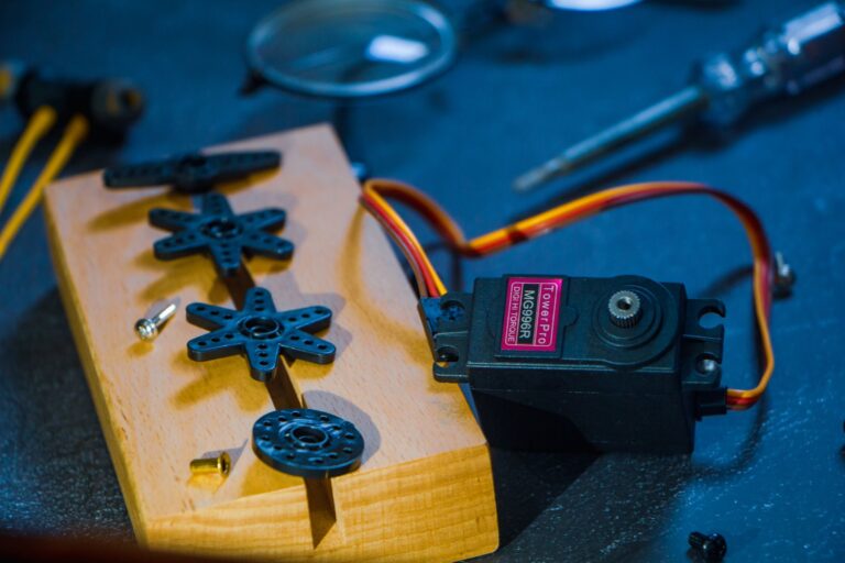
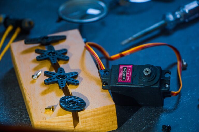
A workable first arm needs a controller, actuators, structure, and power. For the controller, an Arduino Uno or Nano is enough for four to six servos. For actuators, the common beginner mix is an MG996R or MG995 (metal-gear, higher torque) at the shoulder and base, and smaller SG90 or MG90S units at the wrist and gripper, where loads are light. For structure you have three realistic routes: a laser-cut acrylic kit, 3D-printed parts from a published open design, or flat aluminium brackets and standard servo horns. Kits remove the hardest guesswork because the bracket geometry already matches the servo dimensions.
Printed designs give more reach but need a printer and patience with tolerances around bearing seats and horn screws. Power is a separate purchase and not an afterthought. Most hobby servos run on 5–6V, and a single MG996R can pull well over an amp under load. The Arduino's onboard 5V regulator is not designed to supply several of those at once, so plan on a dedicated 5–6V supply — a 2A-or-better adapter, or a battery pack with a step-down regulator. You will also want: male-to-male jumper wires, a breadboard or small terminal strip for distributing power, screwdrivers matching the servo screws, and either a potentiometer set or a joystick module if you want manual control rather than preprogrammed motion.
Assembling the frame joint by joint
Build from the base upward and test each joint before adding the next. The base servo rotates the whole arm horizontally, so it carries the most mass and should be bolted to something heavy and flat — a thick plywood square or a metal plate. An arm that tips over when it reaches forward is usually a base problem, not a code problem. Centre every servo before you attach its horn. Run a simple sketch that commands 90 degrees, then fit the horn and the arm segment at the position you want to be the midpoint of that joint's travel.
Skipping this step is the most common cause of a joint that can only move 30 degrees one way before binding or stalling. Keep the arm short on your first build. Torque at a joint rises with the distance of the load from that joint, so doubling the forearm length roughly doubles the shoulder torque needed to lift the same object. A 15–20cm total reach with a lightweight gripper is a far more cooperative starting point than a 40cm arm that sags and buzzes. Route the servo cables along the inside of each segment and leave slack loops at each joint. Cables pulled taut will either limit travel or get sheared by a moving bracket.
Wiring and the power mistake that kills most builds
Each servo has three wires: signal (usually orange or yellow), power (red), and ground (brown or black). Signal wires go to Arduino PWM-capable digital pins. Power wires go to your external 5–6V supply, not to the Arduino's 5V pin. Grounds from the external supply and the Arduino must be connected together, or the servos will receive no usable reference for the signal pulses and will twitch or sit dead. The failure that catches nearly every beginner looks like a software bug.
Several servos start moving, the Arduino's lights flicker, the board resets, or the arm jitters randomly. That is a brownout: inrush current from the servos drags the supply voltage below what the microcontroller needs. The fixes are separating the supplies as described, adding a large electrolytic capacitor (commonly 470–1000µF) across the servo supply rails near the servos, and keeping power wires short and reasonably thick. Warning signs that your power stage is undersized: If you need more than six servos, or want cleaner behaviour, a PCA9685 servo driver board is the usual next step. It generates the pulses in dedicated hardware over two I2C wires, freeing the Arduino's timers and giving you one tidy place to feed servo power.
- The Arduino resets or the serial connection drops when more than one joint moves
- Servos hum loudly and get hot while holding a stationary pose
- Motion is fine with one servo attached and erratic with four
- A joint moves correctly on USB power alone but not under load
Writing the control sketch
The Arduino Servo library is the baseline. You create a Servo object per joint, call `attach()` with its pin in `setup()`, and then call `write()` with an angle from 0 to 180. That is enough to make an arm move, and it is also enough to make it move badly — a bare `write()` command sends the joint to the target as fast as it can, which jerks the whole structure and can overshoot. The fix is interpolation: step the angle a degree or two at a time with a short delay between steps. Write a small helper function that takes a joint, a target angle, and a step delay, and loops toward the target.
Every motion in the rest of your program then calls that helper instead of `write()` directly, and the whole arm becomes smooth without touching the hardware. Store joint limits in code as constants and clamp every commanded angle against them. Servos will happily try to drive into a mechanical stop, stall, draw heavy current, and strip their gears. Software limits are cheaper than replacement gears, and the MG996R's metal gears survive this abuse better than the SG90's plastic ones, but neither survives it indefinitely. For input, three options scale in difficulty: hardcoded sequences in the sketch, potentiometers or a joystick read with `analogRead()` and mapped onto angle ranges, or serial commands sent from a computer so you can drive the arm from a Python script. The serial route is worth reaching for early, because it lets you test positions interactively instead of recompiling for every change.
What this build can and cannot do
A servo-based Arduino arm is a positioning device, not a precision one. Hobby servos have internal gear backlash and no external position sensing you can read, so the arm goes approximately where you tell it and the error compounds across joints. Repeatability within a few millimetres at the gripper is a realistic expectation for a well-built small arm; sub-millimetre work is not. Payload is similarly modest.
After the arm's own segment weight is accounted for, a small MG996R-based arm typically handles tens of grams to perhaps a couple of hundred at short reach — a marker pen, a ping-pong ball, a light 3D-printed part. Lifting a full drink can at full extension is outside what this class of hardware does reliably. Those limits are not reasons to avoid the build; they define what it is good for. Pick-and-place demonstrations, camera panning, sorting lightweight objects by colour with a sensor, drawing on paper, and learning inverse kinematics are all well within range. If you later need accuracy or load, the upgrade path runs through stepper motors with limit switches and closed-loop feedback — a substantially different and more expensive project.
Adding coordinate control
Commanding joint angles individually becomes frustrating as soon as you want the gripper at a particular point in space. Inverse kinematics is the maths that converts a target position into the joint angles that reach it. For a simple two-link arm in a plane it reduces to trigonometry you can implement in the Arduino sketch using the law of cosines, with the link lengths as constants. Measure your link lengths carefully from joint centre to joint centre — not from the outside of the brackets.
An error of a few millimetres in those constants shows up as a consistent offset at the gripper, which is easy to misread as a servo calibration problem. If the trigonometry on-board becomes awkward, move it off the Arduino. Run the kinematics in Python on a connected computer, send the resulting joint angles over serial, and let the Arduino do nothing but drive servos smoothly to the angles it receives. This split keeps the microcontroller's job simple and makes the maths far easier to debug, because you can print and plot intermediate values.
Frequently Asked Questions
How many servos does a useful robot arm need?
Four is the practical minimum — base rotation, shoulder, elbow, and gripper. Adding a wrist rotation servo makes a fifth and lets the gripper approach objects at an angle rather than only from one orientation.
Can I power the servos from the Arduino's 5V pin?
Only for testing a single small servo with no load. The onboard regulator cannot supply the current several loaded servos draw, and attempting it causes resets, jitter, and possible damage to the board.
Should I use a servo driver board or wire servos directly to the Arduino?
Direct wiring is fine up to about six servos. A PCA9685 driver becomes worthwhile beyond that, or sooner if you want more consistent pulse timing and a single clean point to inject servo power.
Why does my arm sag or drift when it should be holding still?
Usually the joint is beyond the servo's torque capacity at that reach, or gear backlash is letting the load pull the output back. Shorten the arm, lighten the end segments, or move to a higher-torque metal-gear servo at that joint.
You Might Also Like
- What Is New With Simulation Digital Twins Robotics in October 2026? Latest company releases and research papers and Key Takeaways
- What Is New With Research Robotics in October 2026? Latest company releases and research papers and Key Takeaways
- What Is New With Aerial Robots in October 2026? Latest company releases and research papers and Key Takeaways